

Here you can find Sample images and the Resulting 3D model in DroneGIS viewer.
Step 1
From the context menu add images to a Chunk.

Step 2
Align images with default settings
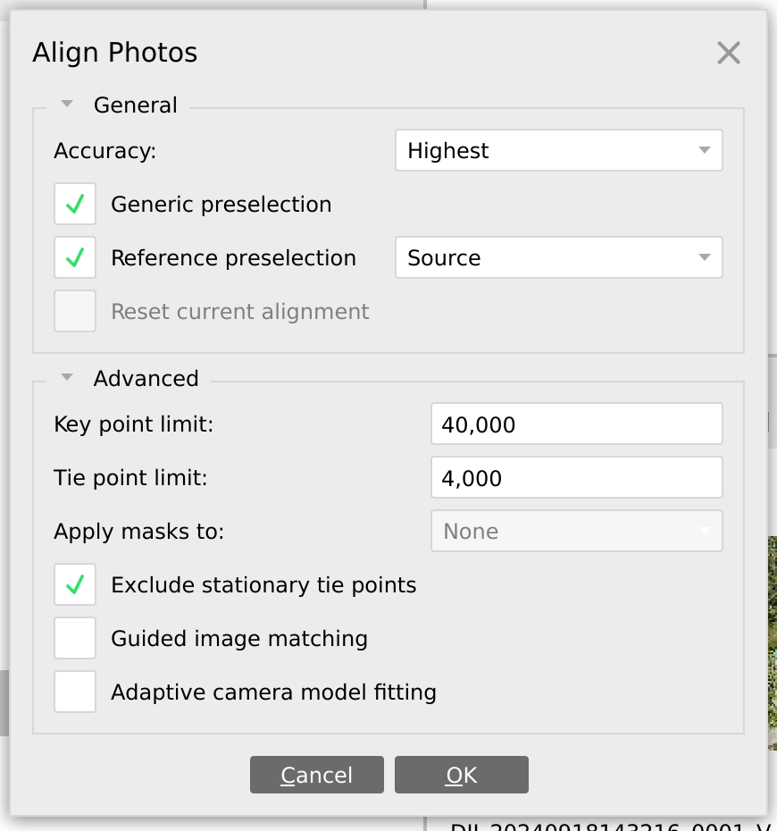
Step 3
If a message regarding oblique cameras appears, proceed as it is.
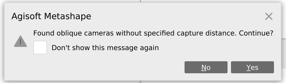
Step 4
After camera alignment, find images that are not aligned. Such images have “N/A” text to the right of the image name.
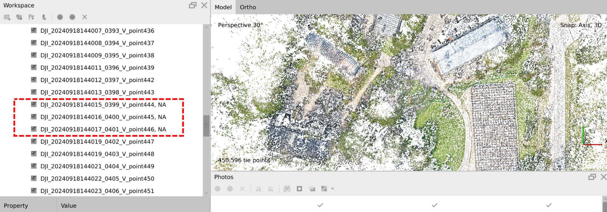
Strategy can be different, depending on the image position:
- If the image is not important for the resulting 3D scene you can simply disable or remove it and exclude it from further processing. YIn the image context menu one may find “Disable Images” and “Remove Images” operations.
- If image plays an important role in the resulting 3D scene, then add tie points between
In many cases, images with vegetation only may not align properly. If these images do not participate in important scenes, it’s much easier just to disable them and proceed with current alignment results.
Step 5
Optimizing tie points which are not accurate is an important step for making your 3D model clean.
This process is iterative and consists of the following steps:
- Use gradual selection and check “Reprojection uncertainty”. If maximum reprojection uncertainty is lower than 10, then proceed to 4.
- Select points with “Reprojection uncertainty” higher than 10, but no more than 50% of points at a time. If 10 selects not more than 50% of points, then Remove selected points, otherwise increase level value.
- Run camera optimization and repeat step 1.
- Use gradual selection and check “Projection accuracy”. If maximum reprojection uncertainty is lower than 2, then proceed to 7.
- Select points with “Reprojection uncertainty” higher than 2, but no more than 50% of points at a time. If 2 selects not more than 50% of points, then Remove selected points, otherwise increase level value.
- Run camera optimization and repeat step 1.
- Finish optimization
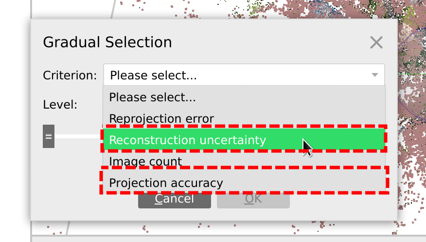
To make gradual selection of points, go to Model -> Gradual selection
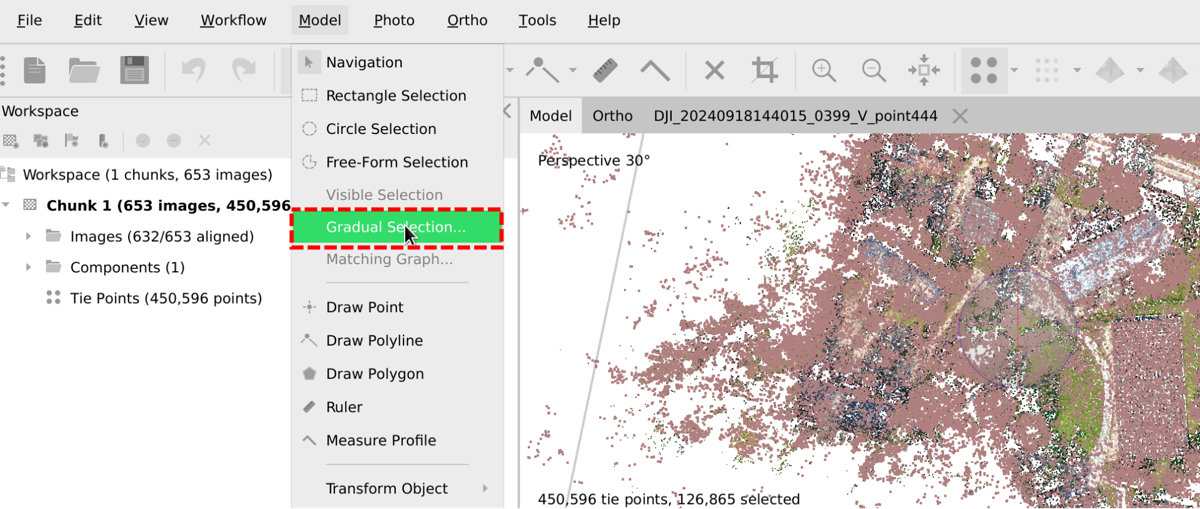
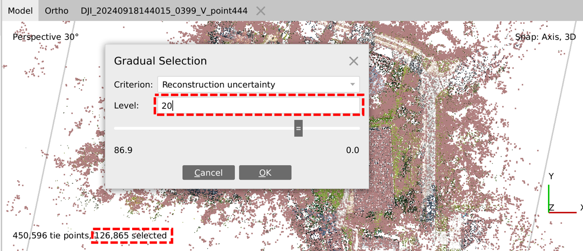
Then, depending on the algorithm step, select either “Reconstruction uncertainty” or “Projection accuracy” and specify a respective Level value.
After changing the Level value, in the bottom left corner of the Model view, you can see the number of selected points. In this particular case 126 865 is less than 50% of 450 596, so we can delete them.
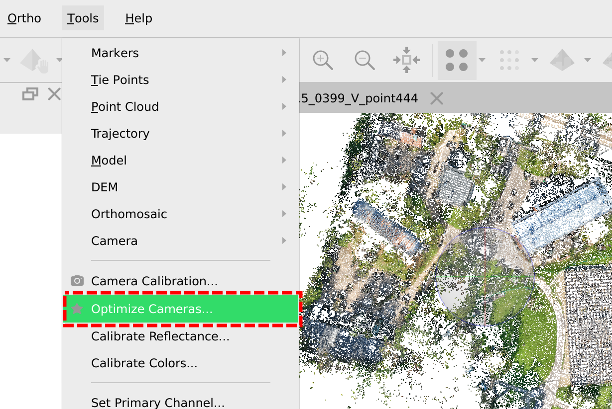
Then optimize cameras using Tools -> Optimize cameras
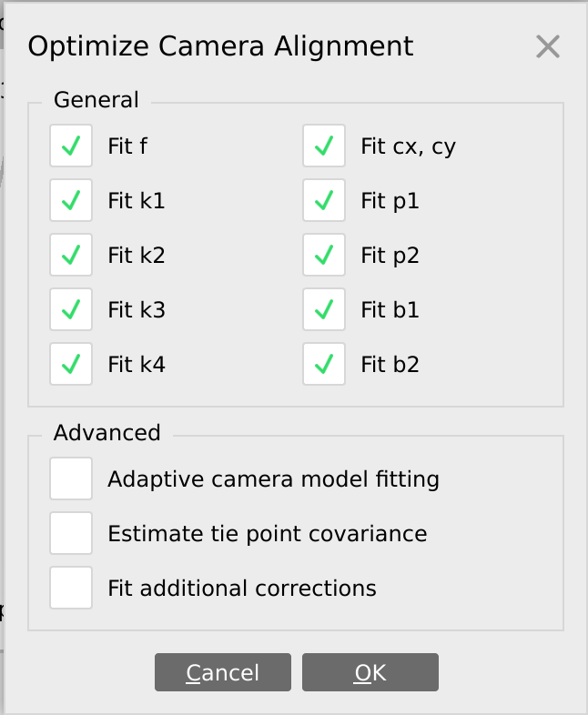
By default you may run optimization with the following parameters
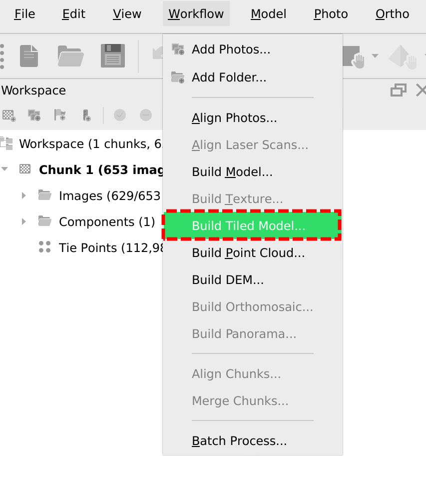
Step 6
Build a tiled model, or any other required product, such as DEM, Point cloud, or regular model.
Step 7
Upload the resulting tiled model to DroneGIS to share with your customer.
- Discover the detailed How to share 3D model from Agisoft Metashape »»»
