Introduction
The test was conducted on the 18th of September 2024 in the SPH Engineering UAV test range in Baloži, Latvia (N 56.8631°, E 24.1119°), where various ferrous (magnetic) and non-ferrous material utilities are buried at different depths. Target detection and data processing were done using Seequent Oasis Montaj software. The devices used in this survey were the ground-based GSM-19W by GEM Systems Inc., UAV-based MagNIMBUS by SPH Engineering SIA and MagDRONE R1 by SENSYS GmbH.
Data was collected by Sergey Kucenko, Maikls Andriksons, Makar Lavish, Matīss Brants. Data processing and reporting were done by Matīss Brants.
Disclaimer: In this context, "detected target" refers to a signal identified by the data interpreter as strong enough to justify further investigation or action. Interpretations are subjective and will change depending on the experience and knowledge of the interpreter.
None of the devices’ manufacturers make any claims or warranty that detection of the same or similar targets is guaranteed under conditions other than in the SPH Engineering test range using the same or different hardware, software, and workflow.
This report is provided "as is" and is intended to demonstrate the capabilities of the system described herein and provide some guidance for planning utility detection surveys.
Data Sets to download
Methods
The UAV test range
The test was conducted at the "SPH Engineering SIA" UAV test range in Baloži, Latvia, a 4-hectare large, open and flat field surrounded by forests in a relatively magnetically quiet area. 23 objects that simulate underground utilities, i.e., steel pipes and barrels, are buried. The ferrous (magnetic) targets technically detectable with magnetometers are listed in Table 1, while their relative positions can be viewed in Figure 1.
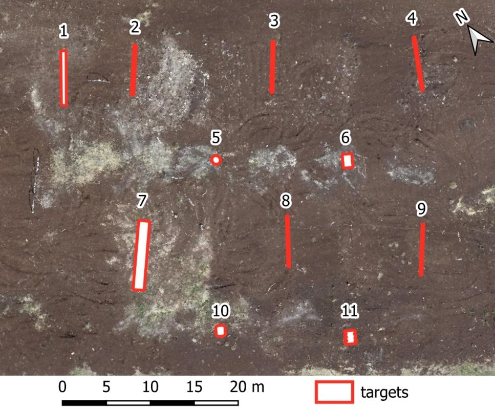
Table 1. Ferrous (magnetic) buried objects in the test range.
Survey execution
The ground-based magnetometer was carried in hand by the operator following a drawn cord, which was moved after every completed line. The sensor altitude above the ground was 0.5 meters and the survey lines were parallel with a separation of 1 meter.
The flight lines for UAV-based survey were planned using the SPH Engineering UgCS (Universal Ground Control System) software, fixing the separation distance of survey lines to 1 meter and accounting for a sufficient run-off at the ends. The sensor altitude for both UAV setups was also 0.5 meters above the ground, precisely set by the laser-guided True-Terrain Following system developed by SPH Engineering.
Devices
GEM Systems GSM-19W with Emlid Reach RS2 RTK GNSS
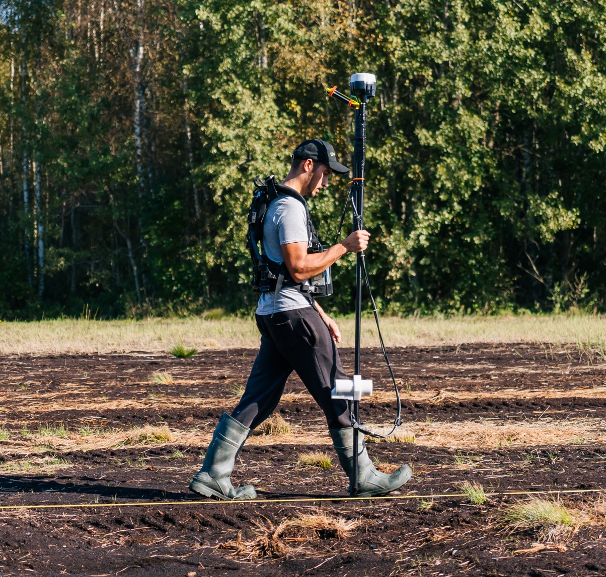
For the ground-based sensor test, the GEM Systems GSM-19W was used (figure 2). It is a total magnetic intensity magnetometer based on the proton precession Overhauser effect technology. This sensor is a very popular and time-proven device with plenty of use cases in mineral exploration and archeology, where durability and sensitivity are paramount. The system is portable, easy and fast to set up; it can be used with a backpack attachment or held in hand, as was done in this test. The sensor altitude of 0.5 meters was controlled by a non-magnetic spacer rod. Due to this setup, the operator wore non-magnetic boots and clothes to eliminate possible magnetic interference.
Originally, the GSM-19W could be used with the provided GNSS (Global Navigation Satellite System) antenna, which determines the horizontal location with approximately 5-meter precision. Although the operator was walking along a drawn cord and thus needed no navigation, the survey data still had to be plotted with precise coordinates. To achieve this, an Emlid Reach RS2 GPS sensor, operating in RTK (Real-Time Kinematics) mode, was mounted 1.3 meters above the system to minimize magnetic interference. The magnetometer measured total magnetic intensity at the highest possible sampling rate of 5 Hz.
SPH Engineering MagNIMBUS
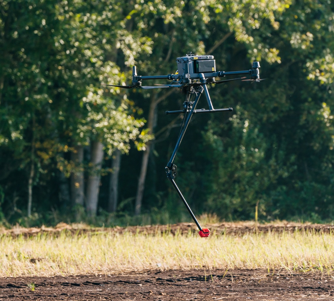
The SPH Engineering-manufactured MagNIMBUS system (figure 3) utilizes a “QuSpin Total-Field Magnetometer” sensor placed at the end of a collapsible "arm" under the UAV, which protects the system from damage in case of a collision with unexpected obstacles and permits extremely low flights with relative safety. The QuSpin sensor records total magnetic intensity at a rate of 250 Hz, which allows it to filter out any magnetic noise picked up from electrical parts of the UAV. Built into the attachment arm is also a 3-component accelerometer sensor which records any sudden movements by the system that could cause errors in the magnetic data. The MagNIMBUS was attached to the DJI Matrice 350 RTK UAV, which utilized GNSS with RTK for precise positioning. The setup was flown at a constant speed of 4 m/s.
SENSYS MagDrone R1
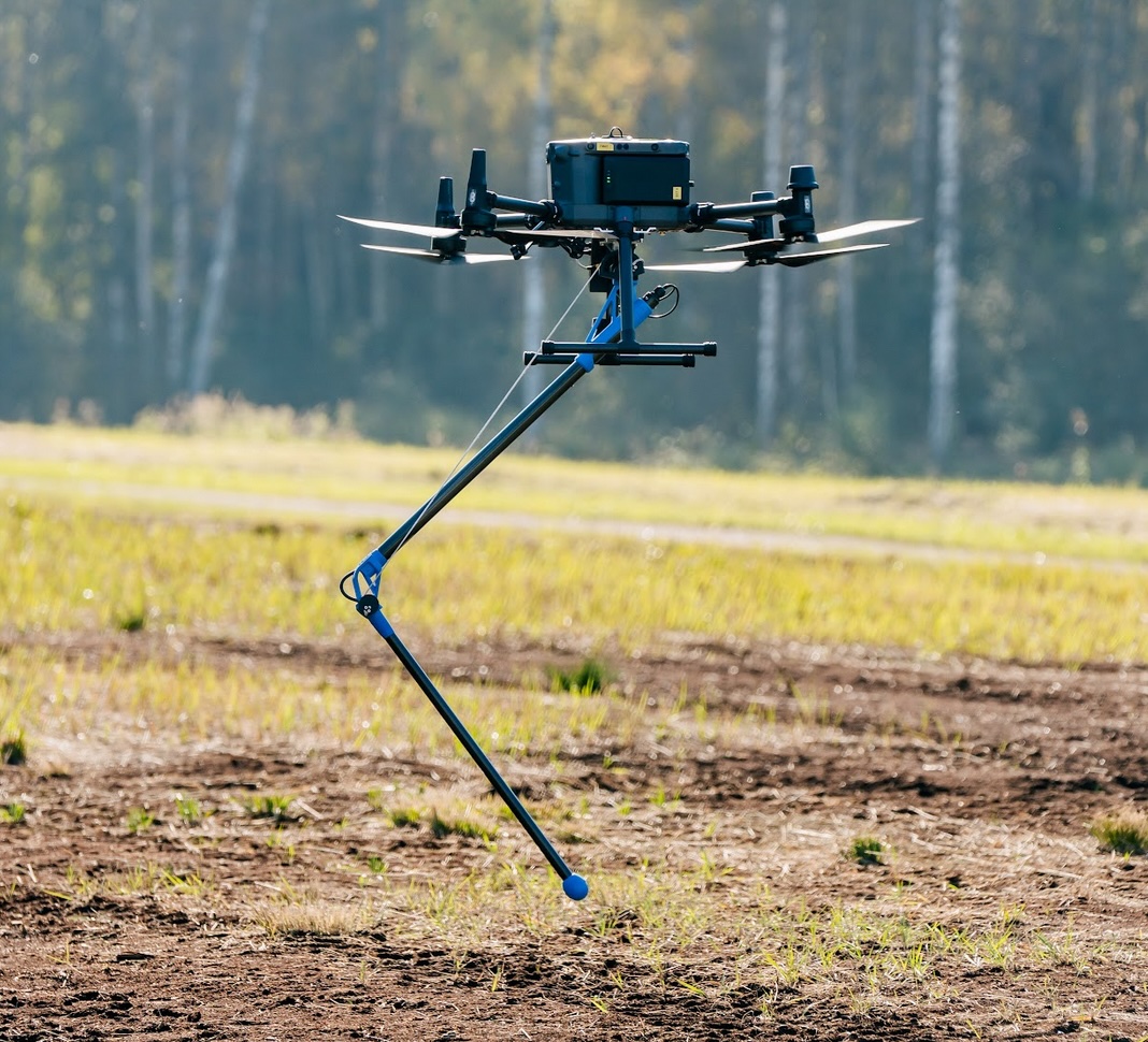
The MagDrone R1 manufactured by SENSYS GmbH is a magnetometer system (figure 4) with a total-field sensor placed on a folding arm to prevent tip-overs or other damage to the system, similar to MagNIMBUS. This setup also permits extremely low-altitude flights to get as close to targets as possible. The system records total magnetic field intensity with a sampling rate of 250 Hz, which allows correction for UAV motors-generated magnetic noise. The MagDrone R1 was attached to DJI Matrice 350 RTK UAV, with GNSS in RTK mode for precise positioning. The setup was flown at a constant speed of 4 m/s.
Data processing
Magnetic data processing was done as similarly as possible for all systems, while still taking into account the different sampling rates. The general workflow is outlined in Figure 5, with a detailed step-by-step account for all setups in the Appendix. The software used was Geosoft Oasis Montaj Standard Edition v2024.1. utilizing only the base module features and well-documented processing methods. All the steps may be repeated with similar results using closed and open-source software.

Results
Survey comparison
The results are displayed as two maps: the residual magnetic anomaly and its analytic signal map. Residual magnetic anomaly is the signal mainly caused by the buried targets after removing other signals and noise. For each target, this anomaly usually manifests as two poles—a negative and a positive one, although it depends on various conditions. To simplify the interpretation, an analytic signal map is generated, which usually shows the targets as positive high values.
All the sensors, ground- and UAV-based, detected all the targets except target no. 9, a thin steel pipe that had never been detected by any magnetometer sensor on the test range. It must be noted that all the sensors detected other small magnetic objects in the test area, which are most likely scrap metal close to the surface.
GEM Systems GSM-19W with Emlid Reach RS2 RTK GPS
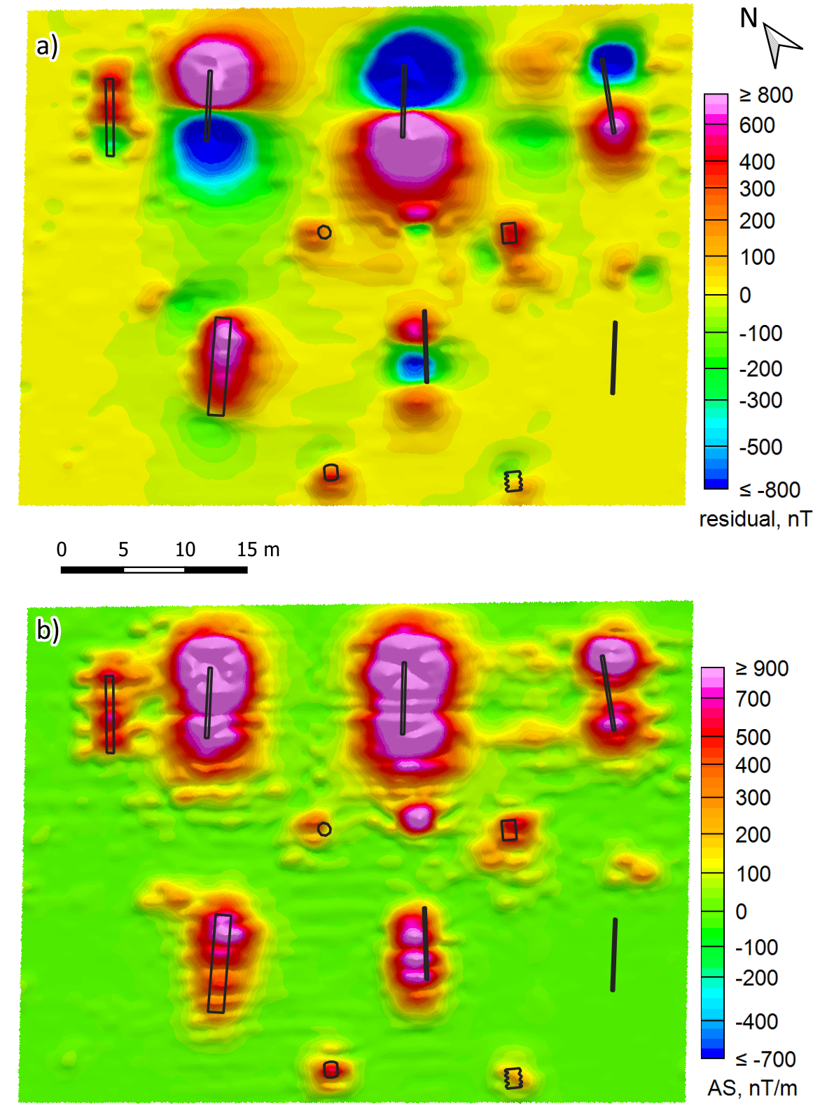
The ground-based GEM Systems GSM-19W sensor detected all of the magnetic targets (Figure 6). The targets (except no. 9) are clearly visible and sufficiently delineated. However, some irregularities in the signal of targets could not be corrected during processing. Those are likely due to the operator's swinging motion while walking.
SPH Engineering MagNIMBUS
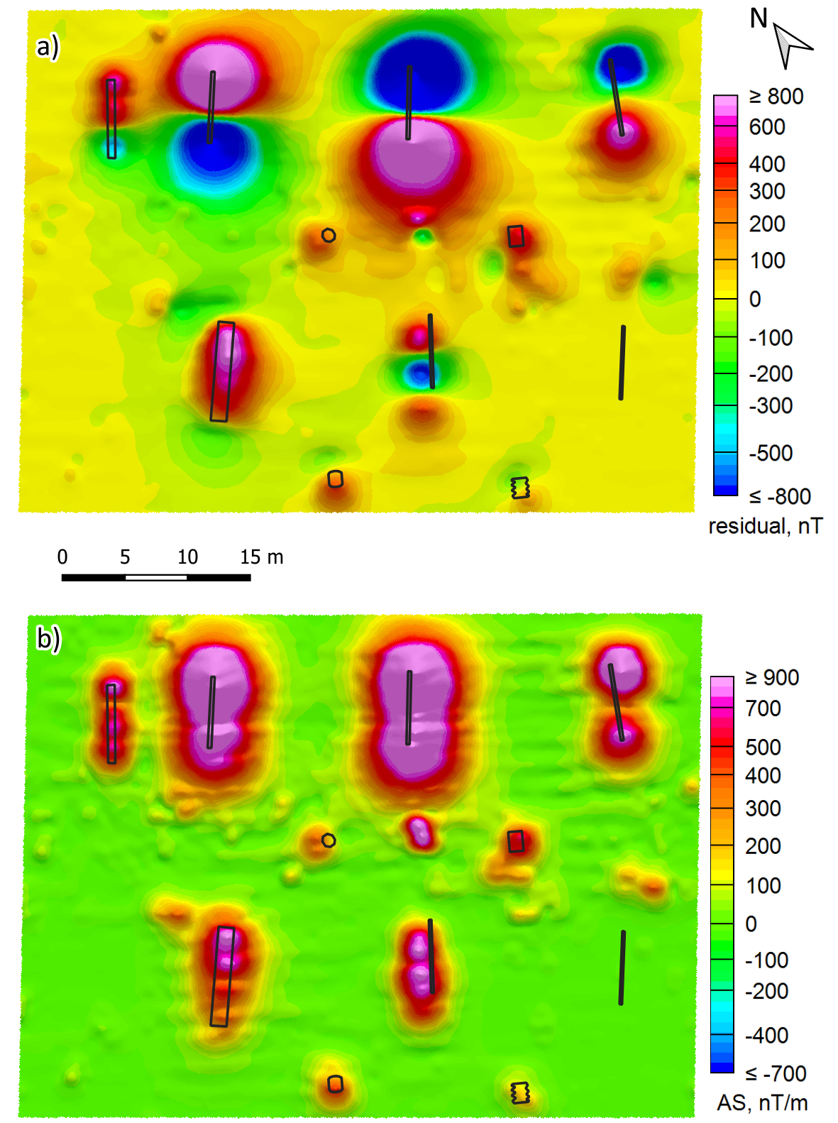
The UAV-based single-sensor MagNIMBUS also detected all of the targets (Figure 7) except target no. 9. The targets are clearly delineated and compact. Some light streaking due to uncorrected heading errors or sensor swaying is still visible, but it could potentially be eliminated by utilizing the built-in accelerometer. This correction feature is still under development.
SENSYS MagDrone R1
The other UAV-based single-sensor SENSYS MagDrone R1 magnetometer performed equally well as MagNIMBUS. The targets were clearly detected (figure 8) and delineated (again, except for target no. 9). There is still some uncorrected heading error visible near the high gradient anomalies, but that is not a concern for this test.
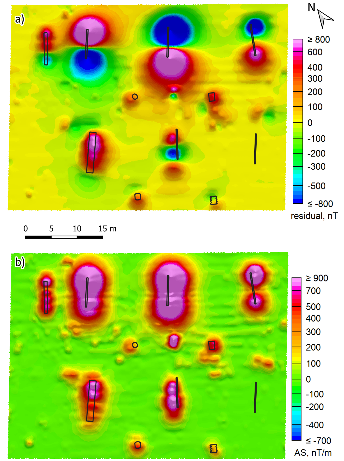
Overall, the sensors showed very similar performance at detecting and delineating the magnetic targets (figure 9). There are no obvious target-detecting advantages for one sensor over the others.

Time comparison
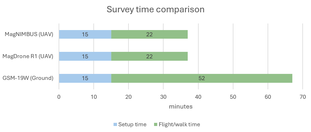
An important aspect of a survey is the time spent on the field, which includes the survey setup time and the actual flight or walk time over the survey area. These times for this comparison are shown in figure 10.
For ground-based surveys with tight line spacing the setup time includes setting out area corner points with RTK-enabled GPS, drawing out a measuring tape at both ends, and a cord across the field for the first line. The setup time for ground-based survey in the present case was approximately 15 minutes. The walking time was 52 minutes, during which a single person was walking and two others were moving the cord a meter after every line. The average walking speed was 1.4 m/s.
Both UAV-based magnetometers were set up in 15 minutes, which included creating a flight path project in UgCS software, attaching the similarly built magnetometers to the UAV and preparing the UAV for takeoff. The flight time from takeoff to landing was also the same - 22 minutes at a velocity of 4 m/s.
The complete survey time for the UAV-based magnetometer system was 45% shorter than for the ground-based magnetometer system: 37 versus 67 minutes.
Precision of the survey lines
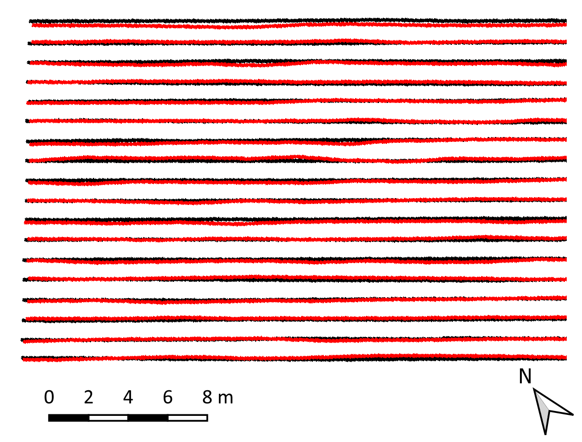
Another important consideration is the precision of movement in straight, parallel lines. The more precise the lines, the better the coverage for surveys with tight spacing (for example, in unexploded ordnance (UXO) surveys). In the present test case, the UAVs could follow the lines more precisely than the human operator (figure 11), although in all cases, the performance was sufficient. Over large survey areas, however, one would have to account for human fatigue as well, while the UAVs would only require regular battery changes. In rugged areas with low vegetation and uneven surfaces, UAVs would have no problems keeping straight lines, while a human operator would struggle to overcome the terrain.
Human resources comparison
In this test case, the ground-based magnetometer system required one operator and two other persons to move the drawn cord after each line. It is possible to draw a very long cord in zig-zags over the whole survey field, which would greatly increase the setup time, while technically requiring only one person. The UAV-based systems technically require only one operator. Still, from the viewpoint of safety and legislation requirements, two persons are needed: a pilot keeping an eye on the UAV remote and flight parameters, while another person oversees the survey area for any potential obstacles and dangers.
Multi-sensor systems
In this test, only single-sensor systems were evaluated. There are many options for multi-sensor systems on the market, both ground-based and UAV-based. These systems, however, are usually considerably more expensive and thus might not be suited for small surveys. Moreover, the added complexities and bulkiness of multi-sensor setups are less attractive for surveys in rugged areas, where maneuverability, compactness and range are paramount. This can be more easily provided by single-sensor systems.
Conclusions
The quality and interpretation of survey results were comparable for all systems – all targets were detected by ground-based and UAV-based systems. However, there were two major differences in the effectiveness between the competitors. The most important one was the time spent on the whole survey, which for both UAV-based single-sensor systems was 45% shorter than for the ground-based one. The second difference was the human resources needed – for the ground-based survey three persons were required, while only two persons were needed during the survey with UAV-based systems. During surveys in large areas one would also have to consider ground-based operator’s fatigue slowing down the survey, while the UAV-based system could fly at even double the speed.
Appendix – data processing steps
GEM Systems GSM-19W with Emlid Reach RS2 RTK GPS
Using Seequent Oasis Montaj:
- Combined the data from GSM-19W magnetometer and Emlid Reach RS2 GNSS;
- Removed faulty measurements*;
- Applied low-pass filter of 10 fiducials;
- Applied Lag Correction of +5 fiducials;
- Applied Rolling median of 190 fiducials (covering the length of the area);
- Generated residual anomaly grid with cell size 0.1 m, and smoothed it with a 9x9 Convolution filter in 3 passes;
- Generated the Analytic Signal based on the residual anomaly grid and smoothed it with a 9x9 Convolution filter in 3 passes.
* The GEM Systems GSM-19W experienced some issues in high magnetic gradient zones (meaning, near strong anomaly peaks), where the magnetic intensity was recorded as ‘0’ in these zones, possibly due to crossing the gradient tolerance for the GSM-19W. This was partially solved by deleting the faulty entries and letting the gridding algorithm cover the no data zones. The test results were only negligibly affected.
SPH Engineering MagNIMBUS
Using Seequent Oasis Montaj:
- Applied low-pass filter of 50 fiducials;
- Applied Lag Correction of -14 fiducials;
- Applied Rolling median of 5500 fiducials (covering the length of the area);
- Generated residual anomaly grid with cell size 0.1 m, and smoothed it with a 9x9 Convolution filter in 3 passes;
- Generated the Analytic Signal based on the residual anomaly grid and smoothed it with a 9x9 Convolution filter in 3 passes.
SENSYS MagDrone R1
Using Seequent Oasis Montaj:
- Applied low-pass filter of 50 fiducials;
- Applied Lag Correction of +22 fiducials;
- Applied Rolling median of 5500 fiducials (covering the length of the area);
- Generated residual anomaly grid with cell size 0.1 m, and smoothed it with a 9x9 Convolution filter in 3 passes;
- Generated the Analytic Signal based on the residual anomaly grid and smoothed it with a 9x9 Convolution filter in 3 passes.


